


Installing a hopper bottom silo is a precision engineering task where the discharge angle, foundation design, and material-specific flow properties determine operational success. Built on 15 years of industrial bulk storage expertise, this guide breaks down the critical technical parameters, a five-step installation workflow, and common pitfalls to help you avoid costly operational risks from the start.
Critical Technical Parameters for Hopper Bottom Silo Installation
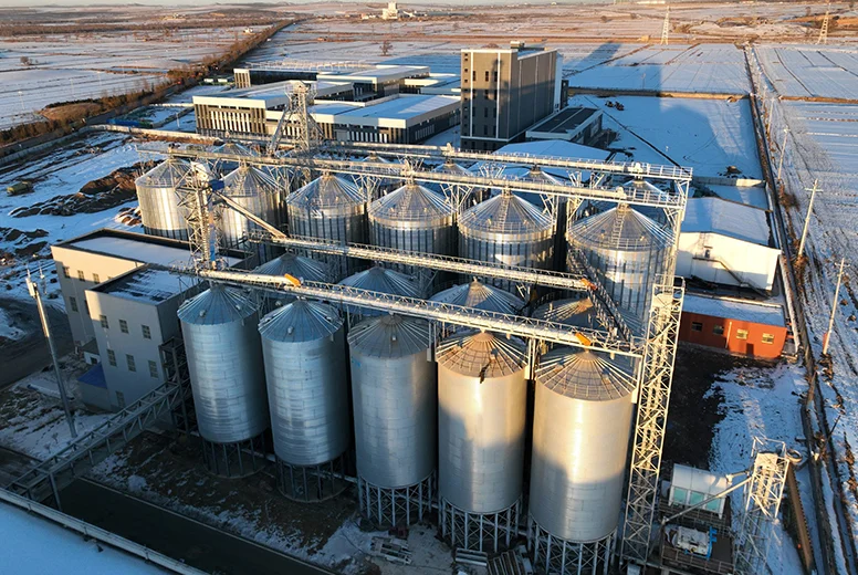
Installing a hopper bottom silo is far more than assembling steel components—it is a multi-variable engineering challenge that must account for material properties, structural mechanics, and site conditions. The hopper angle is the single most important factor governing flow reliability. For free-flowing grains like wheat and corn, a hopper angle of at least 45° is required. For cohesive powders such as cement or feed meal, the angle must be increased to 55°–60° to prevent bridging and arching.
Discharge opening dimensions must be precisely calculated based on particle size and required flow rate: too small invites blockages, too large risks damaging downstream equipment from uncontrolled material surges. Foundation bearing capacity must integrate the silo’s dead weight, live load from stored material, wind load, and snow load. In soft soil areas or high-seismic zones, specialized ground treatment is mandatory. Before any field work begins, our technical team completes detailed 3D modeling and clash detection to verify the exact positions of spiral ladders, manholes, and level indicator ports—eliminating costly rework later.
Five-Step Installation Process: From Foundation to Commissioning
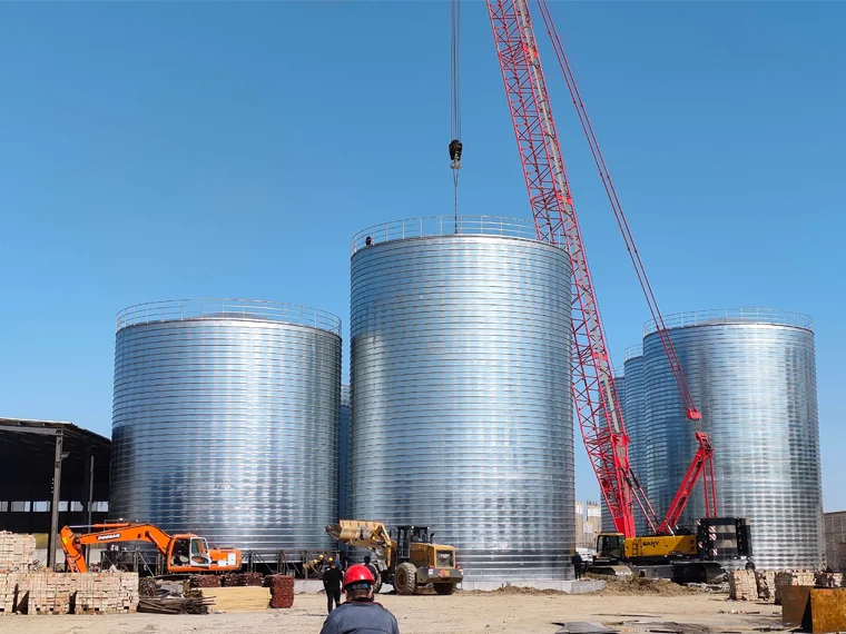
A standardized, well-documented installation sequence is essential for ensuring structural integrity and long-term reliability. The process begins with foundation preparation, where the concrete base must cure to full strength and anchor bolt placement is verified against the 3D model. Step two involves assembling the hopper section—the most critical part—where welds must meet strict quality standards to handle concentrated stress. Step three is the erection of the silo body, using either bolted or welded panels depending on the design. Step four installs the roof, access platforms, and safety railings. Finally, step five covers the installation of discharge equipment, level sensors, and dust control systems, followed by full commissioning tests.
Pre-Installation Engineering: The 30% Rule
Material-specific discharge simulations predict potential flow problems, and these upfront design activities typically consume over 30% of the total project timeline. Thi
s investment dramatically reduces on-site change orders and ensures installation quality from the ground up. Our team uses finite element analysis to validate hopper wall thickness and stiffener placement, ensuring the structure can handle asymmetric loading during discharge.Common Pitfalls in Hopper Bottom Silo Installation
One of the most frequent mistakes is underestimating the importance of the hopper-to-body transition joint. This area experiences the highest stress concentration and must be reinforced with gusset plates or thicker gauge steel. Another common error is improper alignment of the discharge cone, which can cause eccentric flow and structural fatigue. Always verify that the hopper angle is measured from the horizontal, not the vertical, to avoid a 10°–15° error that could render the silo unusable for certain materials.
Key Takeaways
- Key Data: Hopper angles must be 45° for free-flowing grains and 55°–60° for cohesive powders to prevent bridging.
- Best Practice: Invest over 30% of the project timeline in pre-installation 3D modeling and clash detection to eliminate field rework.
- Watch Out For: Misalignment of the hopper-to-body transition joint—this is the highest stress concentration point and requires reinforcement.
- Pro Tip: Always measure the hopper angle from the horizontal plane; a 10°–15° measurement error can lead to flow failure.
- Bottom Line: Proper hopper bottom silo installation hinges on material-specific engineering, not generic assembly—every angle and weld matters.
Material-Specific Flow Properties and Discharge Design
The hopper bottom silo’s performance is directly tied to the physical properties of the stored material. For grains, the angle of repose typically ranges from 25° to 35°, allowing for a 45° hopper to achieve mass flow. However, for cement or fly ash, the angle of repose can exceed 40°, and the material’s cohesive strength increases with compaction. In these cases, a 60° hopper is often necessary, and the discharge opening must be at least three times the maximum particle diameter to prevent arching. Our engineers use Jenike shear testing to measure material flow properties and calculate the critical hopper angle for each specific application, ensuring reliable discharge under all operating conditions.
Foundation Design and Load Considerations
The foundation for a hopper bottom silo must support not only the vertical load but also the lateral forces generated during discharge. When material flows, it creates dynamic pressures that can exceed static pressures by 20%–30%. In seismic zones, the foundation must be designed to withstand horizontal accelerations without differential settlement. We recommend a reinforced concrete ring foundation with a minimum bearing capacity of 150 kPa for standard applications, increasing to 250 kPa for high-capacity silos. For soft soil conditions, deep pile foundations or soil improvement techniques such as vibro-compaction are required to prevent long-term settlement that could distort the hopper geometry.
Frequently Asked Questions
Q: What is the minimum hopper angle required for cement storage in a hopper bottom silo?
A: For cement and other cohesive powders, the hopper angle must be between 55° and 60° measured from the horizontal. This steeper angle is necessary to overcome the material's cohesive strength and prevent bridging or arching. A 45° angle, which works well for grains, will almost certainly cause flow problems with cement, leading to costly blockages and downtime.
Q: How do you calculate the correct discharge opening size for a hopper bottom silo?
A: The discharge opening size is calculated based on the maximum particle size of the stored material and the required flow rate. As a rule of thumb, the opening should be at least three times the diameter of the largest particle to prevent arching. For powders, the opening must also account for the material's cohesive strength, which is determined through Jenike shear testing. An opening that is too small will cause blockages, while one that is too large can lead to uncontrolled material surges that damage downstream equipment.
Q: What foundation bearing capacity is required for a hopper bottom silo in a seismic zone?
A: In seismic zones, the foundation must be designed to withstand both vertical loads and horizontal accelerations. We recommend a minimum bearing capacity of 150 kPa for standard applications, increasing to 250 kPa for high-capacity silos. Additionally, the foundation must be reinforced to handle dynamic pressures that can exceed static loads by 20%–30% during discharge. Specialized ground treatment, such as deep pile foundations or vibro-compaction, is mandatory in soft soil areas to prevent differential settlement that could distort the hopper geometry.
Q: Why is 3D modeling important before hopper bottom silo installation?
A: 3D modeling and clash detection are critical because they verify the exact positions of all components—spiral ladders, manholes, level indicator ports, and discharge equipment—before any field work begins. This upfront engineering typically consumes over 30% of the project timeline but dramatically reduces on-site change orders and rework. It also allows for material-specific discharge simulations that predict potential flow problems, ensuring the installation is optimized for the specific material being stored.
Q: What is the most common mistake during hopper bottom silo assembly?
A: The most frequent mistake is underestimating the importance of the hopper-to-body transition joint. This area experiences the highest stress concentration during operation and must be reinforced with gusset plates or thicker gauge steel. Another common error is improper alignment of the discharge cone, which can cause eccentric flow and structural fatigue. Always verify that the hopper angle is measured from the horizontal plane, as a 10°–15° measurement error can render the silo unusable for certain materials.
Need expert hopper bottom silo installation for your project?
We provide professional design, manufacturing, and installation services for bulk storage and material handling systems worldwide, with 15 years of experience in grain, cement, and industrial applications.
Get a Free Technical Consultation →