


Pressure differential sealing in bulk material handling is the single most critical factor determining pneumatic conveying efficiency and dust control. Yet, many operators overlook the rotor-to-housing clearance in their airlock feeders, tolerating gaps that bleed 15-20% of conveying air pressure. Optimizing this clearance directly impacts system throughput, energy consumption, and particulate emissions.
Airlock Feeder Clearance: The Hidden Leak Path in Pressure Differential Systems
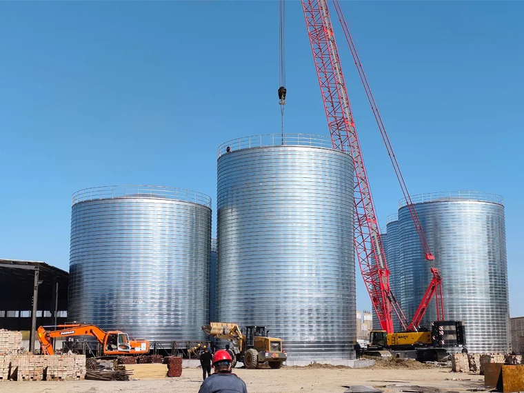
The rotor-to-housing clearance in a rotary airlock feeder is not merely a manufacturing tolerance; it is a dynamic leak path that evolves with wear, thermal expansion, and material abrasion. For a typical 300 mm diameter rotor operating at 15 rpm, every 0.1 mm increase in radial clearance can increase air leakage by approximately 3-5 m³/hour under a 0.5 bar pressure differential. This leakage directly reduces the effective conveying air volume, forcing the system fan to work harder—often consuming 10-15% more energy than necessary. In grain storage applications, where a flat bottom silo with reinforced concrete foundation relies on precise aeration and discharge control, even minor airlock inefficiency can disrupt the entire downstream conveying sequence.
Field data from over 200 pneumatic conveying installations indicates that clearances exceeding 0.3 mm on new rotors are a red flag. Most experienced engineering teams target an initial cold clearance of 0.10-0.15 mm per side for standard carbon steel rotors handling grain or feed. This range balances thermal expansion during continuous operation—where housing temperatures can reach 60-80°C—against the need for a tight seal. The real challenge begins after 6-12 months of service, when abrasive materials like corn, soybeans, or mineral additives can enlarge clearances by 0.05-0.10 mm annually.
How to Calculate and Set Optimal Rotor Clearance for Sealing Efficiency
The fundamental equation for airlock leakage is Q = C × A × √(ΔP), where Q is leakage flow, C is a discharge coefficient (typically 0.6-0.8 for sharp-edged orifices), A is the total clearance area, and ΔP is the pressure differential. For a six-vane rotor with 300 mm diameter and 300 mm length, the total clearance area equals approximately 0.0006 m² at a 0.15 mm gap. At a 0.5 bar differential, this yields a leakage of roughly 8-12 m³/hour. Doubling the gap to 0.30 mm quadruples the leakage area, pushing losses past 30 m³/hour—enough to starve a downstream flat bottom soybean storage silo of conveying air and cause pipeline blockages.
Practical Clearance Setting Procedure
Always measure clearance at four points per vane tip using feeler gauges: both ends and mid-span. Record the average and maximum deviation. For new installations, set the rotor eccentric to achieve 0.12 mm on the inlet side and 0.18 mm on the discharge side—this compensates for pressure-induced rotor deflection. Tighten housing bolts in a cross-pattern to avoid warping the end plates.
Common Clearance Adjustment Mistakes
One frequent error is assuming tighter is always better. A clearance below 0.08 mm risks metal-to-metal contact during thermal expansion, causing galling and catastrophic rotor seizure. Another oversight is neglecting end-plate clearance: the axial gap between rotor end faces and housing side plates often accounts for 30-40% of total leakage. These axial clearances should be set at 0.10-0.15 mm and checked every six months.
Key Takeaways
- Core Data Point: A 0.15 mm increase in radial clearance can triple air leakage, reducing conveying efficiency by up to 18% (based on industry pneumatic conveying standards).
- Best Practice: Set initial cold clearance at 0.10-0.15 mm per side, with a slightly larger gap (0.15-0.20 mm) on the discharge side to account for pressure deflection.
- Risk Alert: Axial end-plate clearances are frequently ignored yet contribute 30-40% of total leakage; measure and adjust them every six months.
Wear Compensation Strategies for Long-Term Pressure Differential Stability
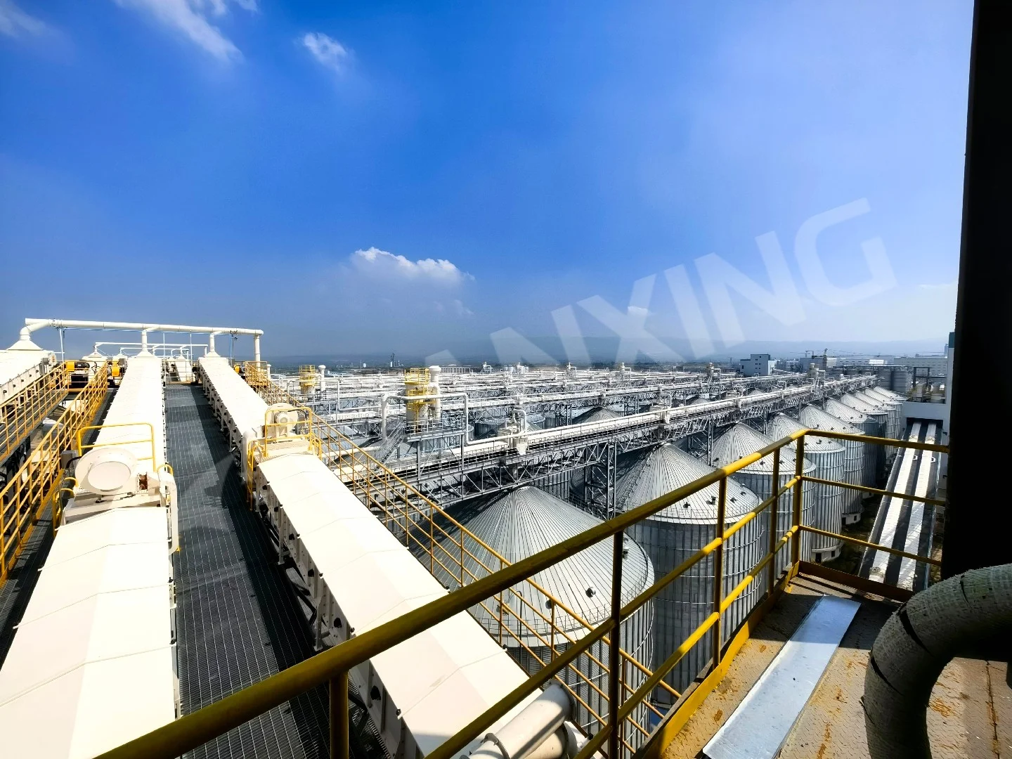
After 18-24 months of operation, rotor tip wear becomes the dominant factor in clearance degradation. For systems handling abrasive grains like corn or wheat, tip hardfacing with chromium carbide overlay (60-65 HRC) can extend service life by 3-5 times compared to standard mild steel. When wear reaches 0.25 mm average clearance, consider rotor reconditioning: grinding the housing bore and installing oversized rotor tips. This approach restores original clearance without replacing the entire airlock, saving 40-60% of replacement cost. In high-throughput applications feeding a flat bottom silo for corn feed storage, scheduled clearance checks every 90 days are standard practice to prevent unplanned downtime.
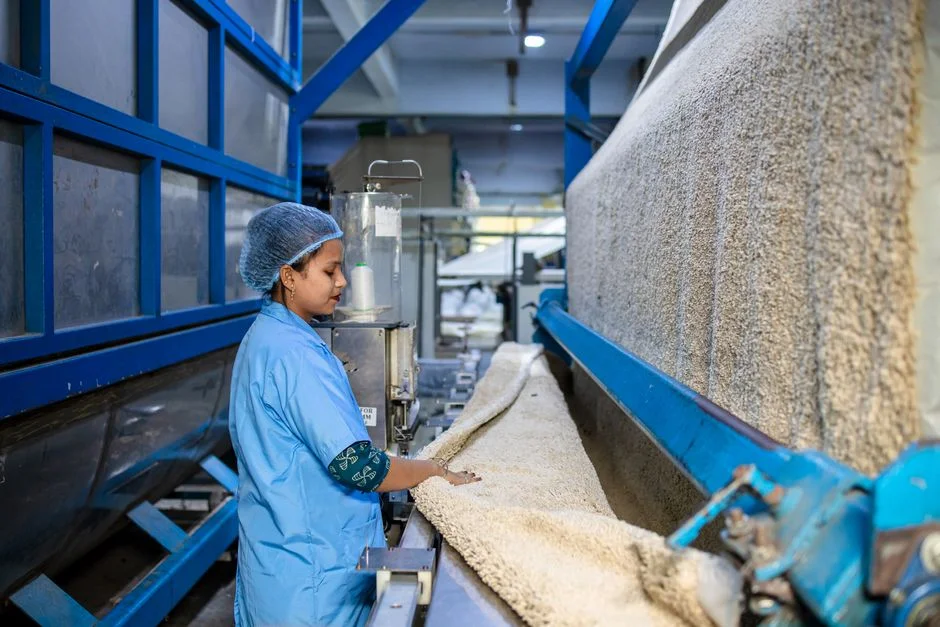
Another effective technique is adjustable housing end plates with replaceable wear strips. These allow axial clearance adjustment without rotor removal, reducing maintenance time from 8 hours to 45 minutes. For systems handling hygroscopic materials like soybean meal, which can swell and increase rotor friction, maintaining clearance at the higher end of the tolerance band (0.18-0.22 mm) prevents binding during high-humidity seasons. A professional silo manufacturer will typically recommend periodic clearance trending: plot measurements over time and schedule intervention when the rate of change exceeds 0.02 mm per month.
Frequently Asked Questions
Q: How do I measure rotor clearance without disassembling the airlock feeder?
A: For an assembled unit, use a lead wire or plastigage method. Place a thin strip of soft lead wire (0.5 mm diameter) on the rotor tip, rotate the rotor by hand through one full revolution, then remove and measure the compressed thickness with a micrometer. This gives an average clearance reading. Alternatively, some technicians use a feeler gauge through the outlet opening while blocking the rotor with a wooden wedge—though this method is less accurate for measuring dynamic clearance under load.
Q: Can I run an airlock feeder with 0.4 mm clearance if I increase the system pressure?
A: This is a dangerous misconception. Increasing system pressure to compensate for leakage actually worsens the problem because leakage flow increases with the square root of pressure differential. At 0.4 mm clearance and 0.7 bar, leakage can exceed 50 m³/hour—enough to cause severe product degradation and pipeline erosion. The correct approach is to restore clearance to 0.15-0.20 mm, then optimize pressure to the minimum required for conveying velocity. Running oversized clearances also accelerates housing wear due to particle entrainment in the leak path.
Looking for Professional Silo Storage Solutions?
We provide customized design, manufacturing, and installation services for steel silo systems worldwide, including precision-engineered airlock feeders for pressure differential applications.
Get Your Free Technical Consultation →